
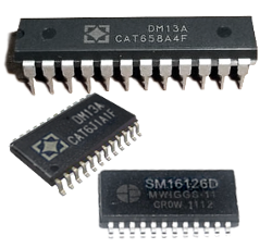
Another option for driving multiple LEDs in a SimVimX system is to use DM13A constant current LED drivers, which are the same latch shift registers as the 74HC595 but have 16 outputs, use a common anode connection for the LEDs, and do not require additional resistors for each LED.
Instead of the DM13A driver, you can use any other similar drivers listed here.
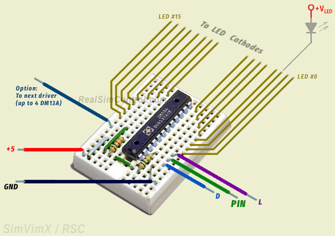
The wiring is quite simple - you need to connect common GND, 3 signal lines - two common "D/L" lines and one control signal "PIN" connected to the pin assigned in the config tool or multiplexer output:

The driver has 16 constant current outputs and each single output can sink the current by 3 ... 60 mA. The LED operating current can be set with one reference resistor connected to the Rext input (terminal #23), that can have resistance between 1 ... 22 kΩ and defines the current (and brightness) for all LEDs. You can connect a variable resistor to adjust the current as needed and then replace it by a constant resistor.
The driver chip itself can be powered using +5V output pin located on the master board, but you amust use a dedicated source (+Vled +5V) for all LEDs powering. The amperage rate of this power supply must be sufficient to power all connected LEDs, for example, if one LED draws 20mA and you have 100 LEDs, the power supply must be rated at 2A, assuming they can all be lit at the same time.
Of course, you can simply use the same dedicated power supply +3.3 - 5V for all LEDs (+Vled) and chip's VDD (in this case don't connect VDD to the +5v pin on your Arduino!, only the GND should be wired together!).
If you think you need to make PCBs for each driver or driver set, no, you don't necessarily need them. You can use a bare DM13A chip inserted into the small "breadboard" that can be taped to any part of your cockpit, or simply glued near to the group of LEDs ( see an example).
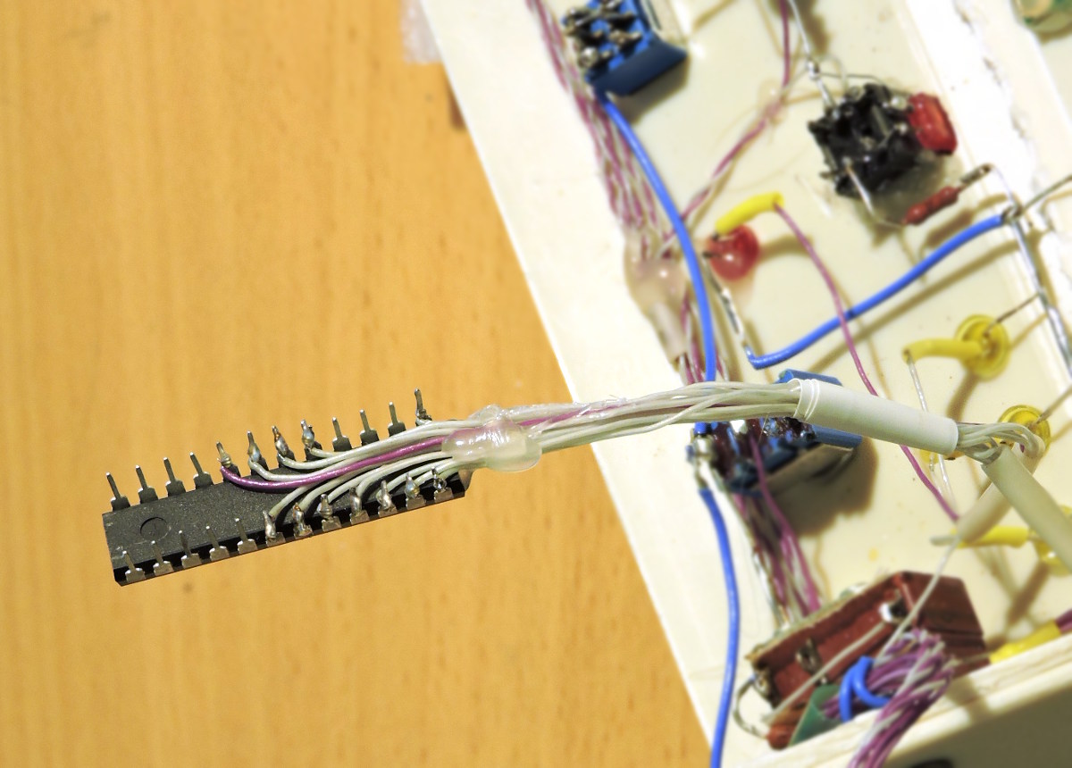
Also, using DM13A drivers in DIP casing, you can solder thin wires directly to the driver pins. Then this driver can be attached to the surface near the LED group using thermo-glue or 2-side duct tape.
See more tips about wiring your cockpit on the "Wiring" page.
In SimVimX system you can have from 8 to 64 serial LEDs connected to one output, depending on the location of LED groups in your panels. For example, you may have 16 LEDs controlled by one single DM13A driver connected to one pin, and another group of 30 LEDs controlled by 2 daisy-chain connected DM13A drivers on another pin.
The maximum number of LEDs with serial shift control on one output is 64, for that you can use 4 daisy-chain connected DM13A drivers. For this you need to use the driver's Dout terminal #22 as "D" input signal for next driver in chain:

As such, you can have either one or several separate LED groups located in different areas of your cockpit. Each group has 3 input signal lines (besides power lines). You need to connect the "PIN" input to the Master board pin assigned as extended output for this group of LEDs. Two other signal inputs - "D" and "L" - should be connected to the corresponding common bus lines ("D" and "L" output signals).
As the LED drivers alternative, you can use 8x shift registers, such as 74HC595 chips or breakout boards.
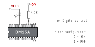
Same as for direct outputs, you can use a serial output as "On/Off" control signal for other circuits, relays, MOSFETs, etc.
For this, instead of LED, use a pull-up resistor 1k connected to +5v bus and use this terminal as output pin for digital control. In the picture you can see that output terminal #16 is used as digital output (all others can be used either for LEDs or digital outputs as well).
LED CONTROL OPTIONS
74HC595 Shift Registers DM13A LED Drivers MAX7219 LED Matrix Direct Connection LED Bar Graph Indicator MUX Output as LED extension LED Configuration