
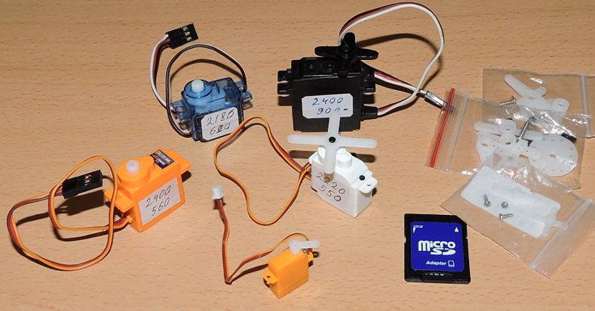
Using small RC hobby servos is an easy way to create most of mechanical instruments/gauges for your home cockpit. The only drawback can be that servos have some noise and limited range of shaft rotation (typical 180°)
As for noise, it is noticeable only at high speed, if the gauge is intended to show a slowly varying value, the noise will be insignificant. You can also find servos with minimal noise. The limited range can be increased by adding a step-up gear (see desctoption below).
A typical servo has a small DC motor with metal or nylon drive gears to reduce rotation speed and increase torque. The output shaft can be rotated to a specific angle (or moved to a specific position for the linear servo) according to the pulse signal width.
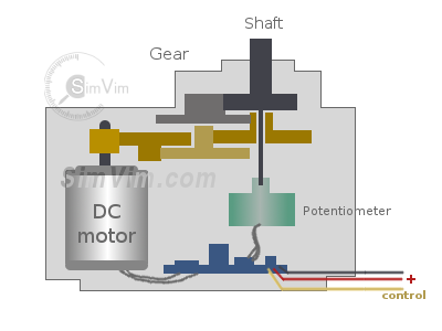
To properly control the servo drive, its internal circuit must receive a pulse every 20 ms. The width of this control pulse determines the angle of rotation for the servo and it can be in range of 0,5-2,5 ms (500-2500 us). Note that this range can vary for different brands, it can be 400-2000, or 1000-2500 etc. Even if you have several servos of one manufacturer all of them may have slightly different control ranges.
The potentiometer on the shaft and a control circuit allow to monitor the angle of the shaft and turn the motor in the correct direction until the angle is correlated with the pulse width.
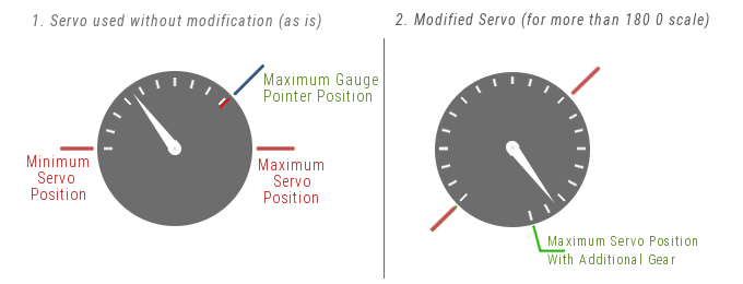
Typically, a servo has 180° rotation range. If your gauge has lesser angle range (as some fuel gauges or some engine parameters gauges), just use a part of full servo shaft rotation. Print the dial for chosen instrument on the paper, place it on your servo, attach an arrow. Then calibrate this gauge in the SimVimX plugin.
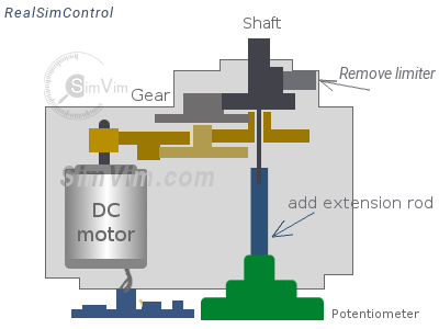
Keep in mind that the minimum and maximum position value number can be correlated with the leftmost and rightmost positions of the servo arrow, or vice-versa. It depends on the particular servo model.If your instrument has a dial scale larger than 180° you can increase the angle range using 2 methods:
Replace the internal potentiometer with another one with a large rotation angle (270-280°). You will need to remove (or change) the limiter for the output gear. The large potentiometer can be placed outside of servo casing. Make sure that the potentiometer's resistance change is linear, and that it has the same max resistance value as the original one. This is a very good method to use, especially when using a high-precision potentiometer.
Adding external step-up gear (e.g., 1.5:1 or 2:1 ), this method doesn't require to disassemble the servo, you need to find a couple of suitable gearwheels and make a support constuction for gear. Gear ratio can be from 1.5/1 to 2/1 to extend the servo rotation angle by 90-180°. Do not make the rotation angle of more than 360°.

You can try to extend the shaft of the penultimate (previous) gearwheel, to use it as the new output shaft to provide larger rotation angle.
However, it is likely that using this gearwheel will make the arrow rotation angle much larger than 360°, depending on the last gears ratio.


Here is the video showing a modified servo, with an output shaft placed on the penultimate gear. This video not represents X-Plane dataref output, the servo is controlled with test program using potentiometer.
Note that the ratio of the final gears in this servo was more than 3:1 and with skipping the last gear the rotation angle was increased from 180° to 580°. Thus, when using this modified servo for a gauge with a scale less than 360°, not the entire range of the servo is used..
>This example uses one encoder attached to the trim wheel and a servo that rotates the disk with the scale. The servo used here Rudder trim position indicator :
