
The SimVimX System uses an additional slave Arduino board as a stepper motor controller. This is an Arduino Nano or Uno board with a special firmware "SimVimX Stepper", which must be loaded onto the board once from the SimVimX Plugin menu.
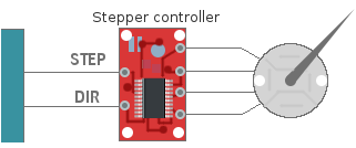
Any stepper motor is connected to the SimVimX Stepper Board only through a special driver/controller, which is suitable for the selected stepper motor and must have only these 2 control inputs - STEP and DIR (also can be marked as Clock and CW/CCW).
Please note that this is NOT like the ULN2003, which is generally used as a simple current amplifier between the low current outputs of the microcontroller or driver and the high current motor.
Currently, two types of stepper motors can be used natively in the SimVimX system:
1) The group of low-power bipolar motors used in car instrument clusters (e.g. X27.168 and similar). These motors are suitable for replicating most aircraft pointer instruments and are used with VID6606, STI6606Z, AX1201728SG, STI6608 drivers, designed specifically for these motors with very low current consumption.
2) 28BYJ-48 (5V version) stepper motor with gearbox can be used in SimVimX with the A3967 controller in full-step mode. This motor is much slower, but cheap and easyly accessible and can be used for many aircraft pointer instruments.
Also it is possible to use other stepper motors. Be aware, though, that most of them require much more power to run, in terms of current consumption or operating voltage. Use only appropriate drivers and power supply for powerful steppers!
To synchronize your instrument with the simulator when loading the aircraft by determining the initial (zero) position of the instrument pointer, two methods are used: a mechanical stopper or a zero position sensor (switch or optocoupler).
When SimVimX is started or reconnected, the firmware program moves the shafts of all motors until the needles/cards cross the position sensor or reach a mechanical stopper. The program then resets the position counters and moves all pointers to their current positions as determined by the simulator.
The mechanical stopper/limiter can be used for most aircraft gauges that have a partial, sectoral dial, when the needle can only rotate in the range of less than full 360 degrees.
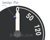
X27.xx stepper motors have an internal mechanical limiter (stop pin), that allow you to use these steppers for any instrument with rotation up to 315 degrees without any modifications.
Any other stepper motors also can be used for sectoral gauges without any sensors, with the addition of a small pin that stops the needle rotation in the leftmost position.
Even for high torque motor the stoper pin for the needle can be used, if you fix the needle to the shaft freely enough to let the shaft to continue its rotation when the needle is stopped by the pin.
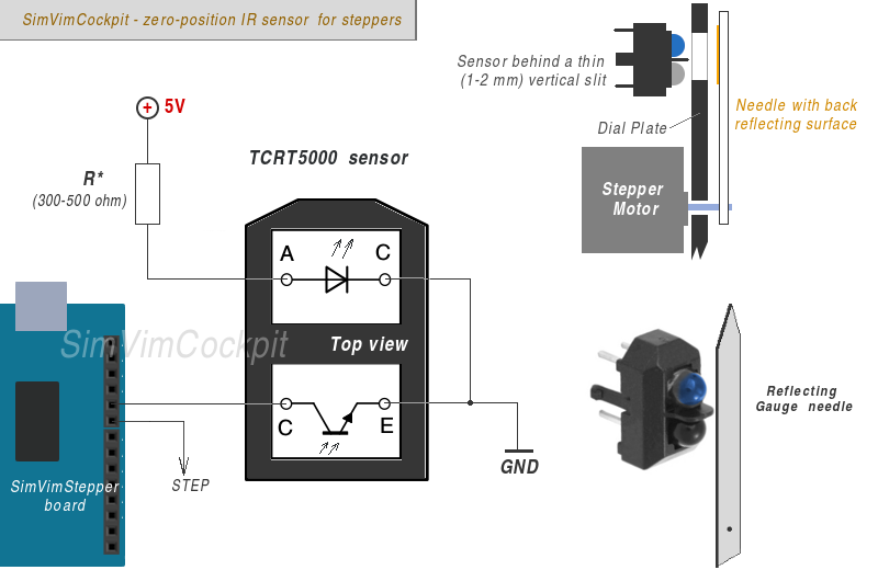
For instruments with continuous rotation of 360 degrees (heading, navigation), the most applicable is an optical positioning sensor using an infrared LED paired with an IR phototransistor, where the white pointer deflects light from the LED to the IR sensor when passing over.
As an example the TCRT5000 sensor is shown on the diagram (you may need to test various resistor value that works for you).
Place the sensor behind non-reflecting, not transparent material that has a thin (0.5-1 mm) vertical slit, to exclude unwanted reaction. Don't place this slit it in the exact "zero" position, it may be shifted slightly CCW by half of the needle width, because it will "catch" the moment when the needle just starts to cross the sensor window.
For instruments that have a rotating disc (card), paint the back side of this card black-matte leaving thin (0.5mm) strip of reflecting surface in "zero" or "north" position.
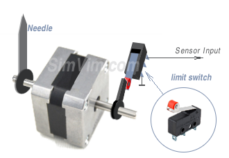
For some limited-sector gauges, a soft momentary limit switch can be used as a simple position sensor if a mechanical stop is not an option for some reason.
!!! If there is no working sensor, the pointer will rotate counterclockwise on reload and then take the wrong position.
The SimVimStepper slave board is connected with the master board, getting data intendent for the steppers. The internal code of the slave board is fully dedicated to generate correct positioning, speed/acceleration move for multiple stepper motors. SimVimX plugin monitors simulator parameters and translates them into signal sequences for every connected stepper motor. Firmware receives that data and converts them into specific stepping pattern for every motor, keeping track of amplitude and speed of change, simulator FPS rate and code loop timing, to eliminate jumps and ensure smooth movement.

The "slave" controller board (Uno, Nano) is linked with the Master controller board using serial interface, when Tx output signal of one board is connected to the Rx iput of another board.
For the stepper control the Tx1,Rx1 ports are used in SimVimX . So, you should always connect the Tx pin (#1) of the slave board with Rx1 pin (#19) of the master board, and "slave" Rx (pin 0) - with the "master" Tx1 (pin #18).
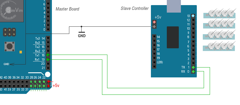
Note 1. Never forget to connect the GNDs of each board ( and other devices as well) to the common GND wire.
Note 2: When you need to upload stepper control firmware to the slave board you need to disconnect the Rx,Tx wires before uploading! To simplify this you simply can add a "shut-off" switch breaking this two wires.
Another option - you can leave the Rx/Tx connected, but press the Reset button on the master board and hold it while uploading stepper firmware to the slave board.
The slave board receives all data from the master controller board only. So, you don't need to keep it connected to USB port after the SimVimX Stepper firmware upload. You can use any +5V source connected to the slave board using USB connector, or +5V pin. It can be the same source that is used for feeding the stepper motor controllers (AX1201728SG or VID6606, STI6608).
