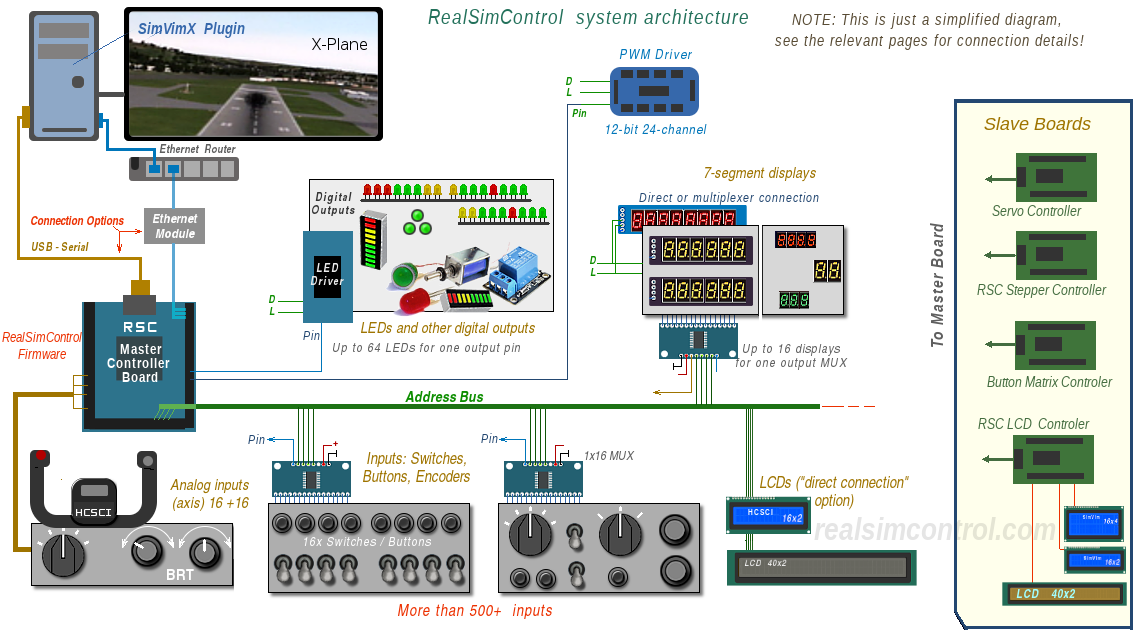
Architecture
The SimVimX System is a hardware interface designed with a bus-based architecture, making it well-suited for environments with widely distributed components, such as a simulator cockpit. The central control unit of the SimVimX System is a single "master" controller board Mega2560 (Arduino2560) with SimVimX firmware uploaded to it only once (or on next firmware update ).
System Capacity
- All toggle, momentary, rotary switches and encoders are connected to the system using simple input extension boards (multiplexers, totally up to 40), providing 500-600 digital inputs. Also, direct connection can be used for simple cockpits.
- More than 1000 LEDs can be connected using the LED drivers, up to 64 LED for each extension, connected directly or to Output Multiplexer. Also, direct LED connection is allowed for few LEDs.
- Up to 64 seven-segment displays can be connected to the system, using output multiplexers extension (displays along with LED drivers). A few displays can be connected directly to the master board.
- Additional "slave" controller boards (Arduino Nano/Uno) are used: 1) for servos (up to 32), 2) for stepper motors (8-19 motors now), 3) LCD displays (12 LCDs) and 4) key matrix inputs (+176 buttons). More slave boards can be added in the future.
- Also, any number of character LCDs can be used with "direct" connection, in case if you don't want to use the slave LCD board and have many free pins, or 12 LCD on the slave board is not enough.
- You can connect up to 24 PWM-driven moving-coil gauges or other PWM controlled devices or LEDs using one TLC5947 PWM driver. Up to 15 PWM devices can be used with master board PWM output pins directly if you have free pins not assigned to inputs/outpus.
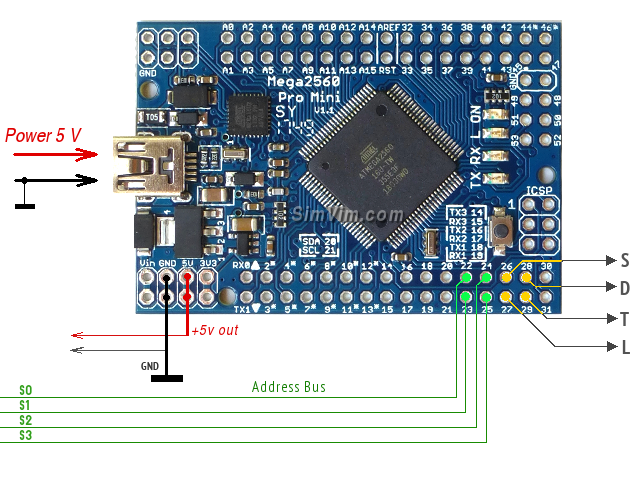
Functions of the Control Port pins:
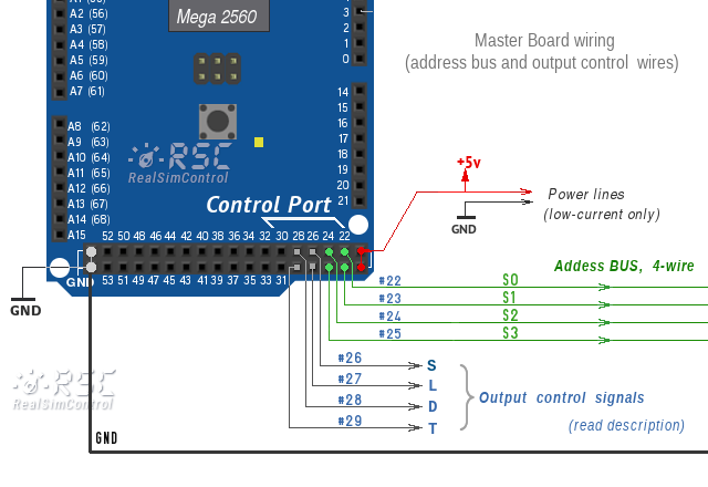
- Pins #22,23,24,25 are used as four address lines (S0, S1, S2, S3) for all multiplexer boards and directly connected LCDs.
- #26 - "S (SIG)" Output port for OUTPUT extension boards only
- #27 - "L" - Control signal for 7-segment displays (except TM1637), Serial LEDs, PWM board
- #28 - "D" - Data signal for 7-segment displays (except TM1637), Serial LEDs, PWM bpard and LCD displays.
- #29 - "T" - Control signal for TM1637 7-segment displays only
- The pin pairs #14,15 / #16,17 / #18,19 can be used for serial communication with slave driver boards (steppers, servo, LCD, matrix).
NOTE: The +5V output pin can be used as a source for all multiplexers connected to the system bus. Also it can be used to power few low-current output devices. See more detail about system powering here.
You can create a flexible modular system and have full set of input controls for any complex cockpit and easily expand it by adding more extension modules at any time.
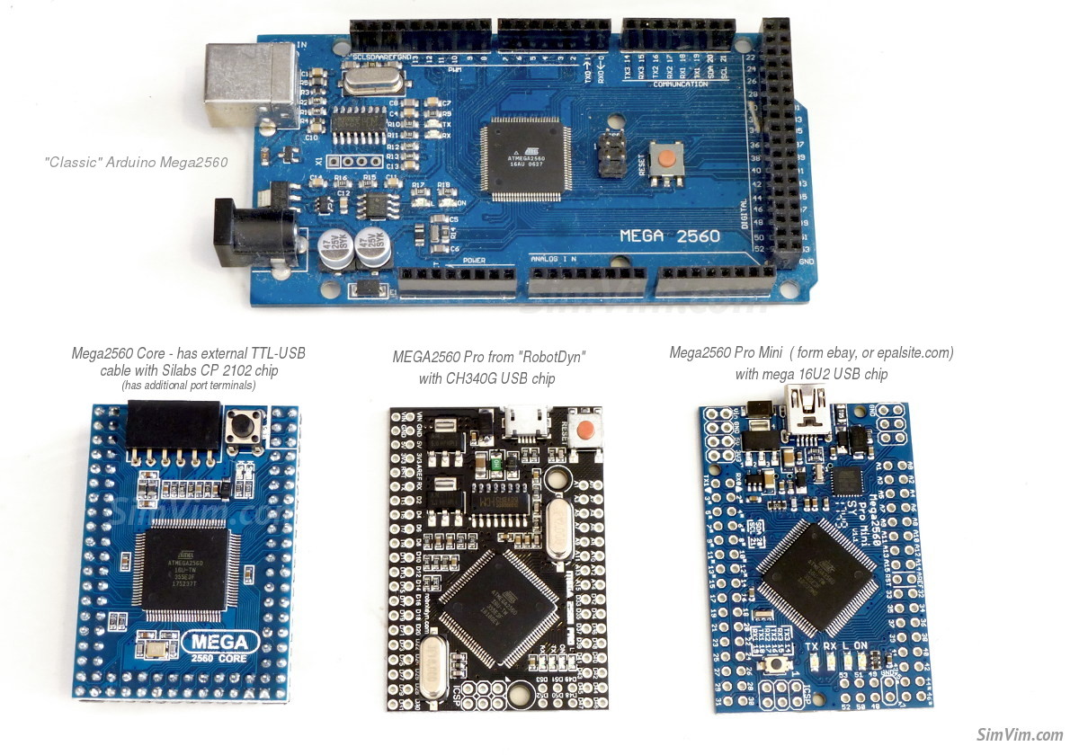
Alternative Mega2560 boards
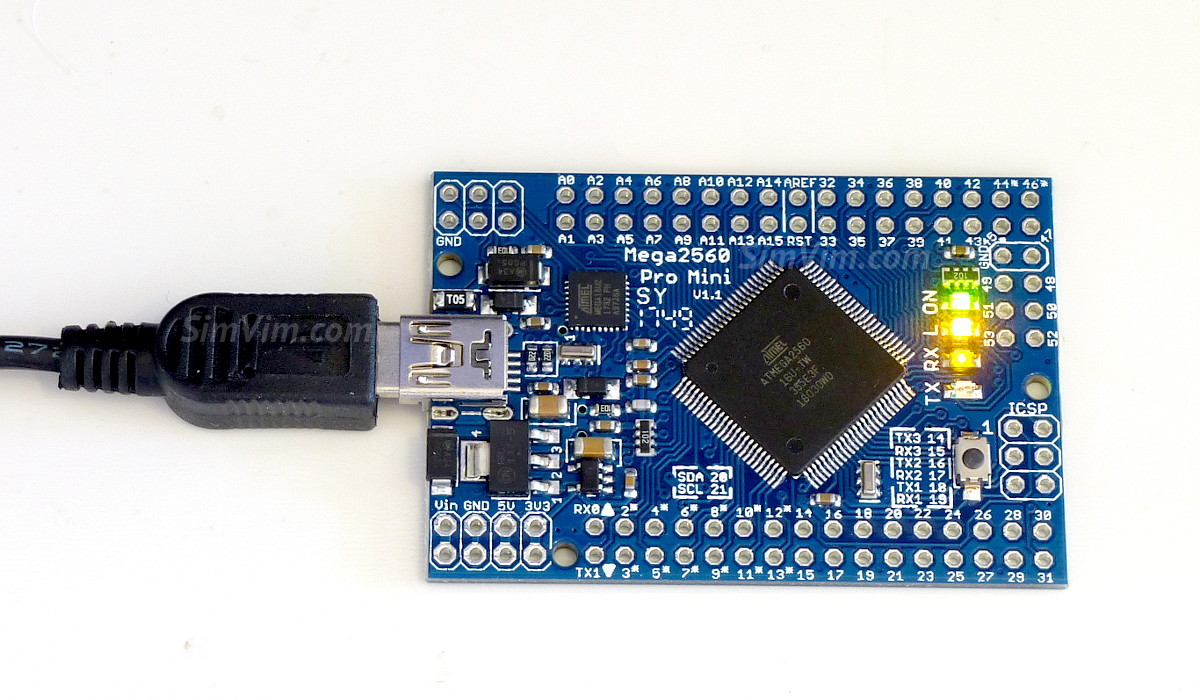
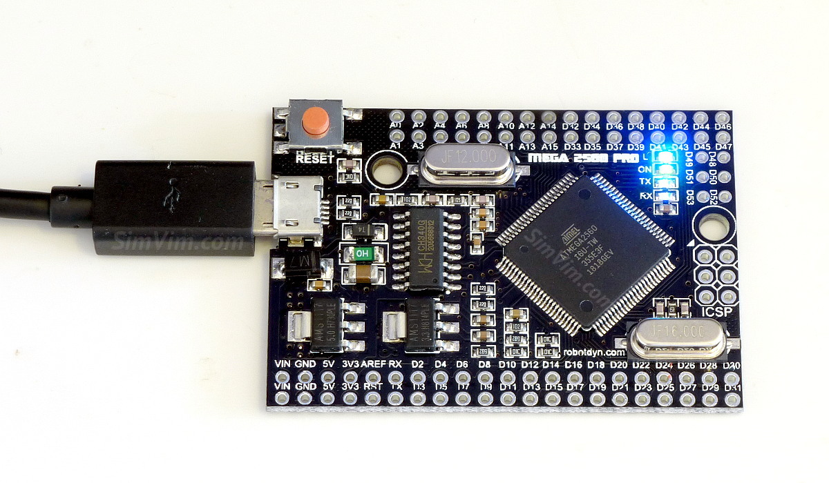
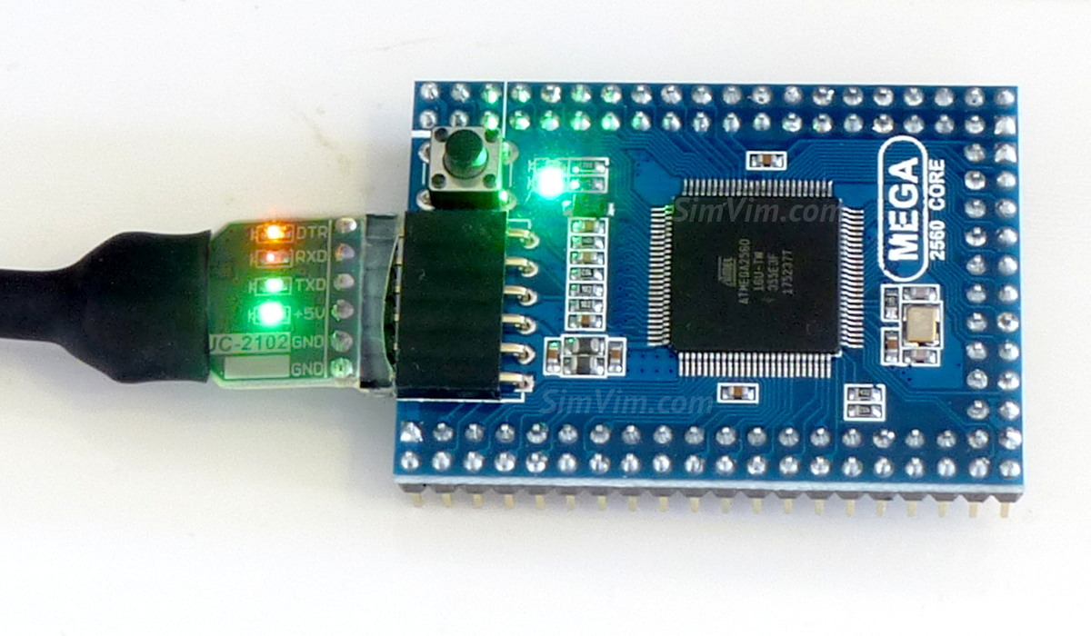
You can use any of the Mega 2560 based controller boards available on the market. In the photo you can see three mini controller boards that are tested with SimVimX, the firmware was uploaded to every of these boards from SimVimX plugin menu without any problems.
There are some other atmega2560 controller boards on the market like "Crumbuino-Mega", various "core" modules. You can find them yourself using such keywords as "2560 core", "atmega2560 mini", etc.