In SimVimX plugin, most parameters related to Radio devices are represented by special SimVimX functions. You don't need to have a plane model that supports a specific type of radio panel, as all its functions work independently of the plane model.
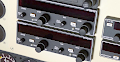
Radio stack modules
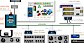
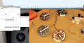
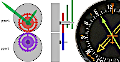
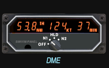
Various radio panel sets can be combined from any of the radio devices currently available in the SVX collection. Here is one of the possible combinations:
All input and display output radio functions work differently depending on the specific device type and currently active mode. This means that you will get the full device functionality by assigning just a single parameter for each input and output related to COM, NAV, ADF, DME and Transponder devices, without the need to assign any conditions for them.
You can select a specific device type when assigning parameters in the configurator. When you use the image map configurator page, device types will be set automatically depending on the image you've selected. For SimVimPanel, the types are already specified in the panel modules.
On connection, device types are passed to the plugin as startup options, and are used to determine how exactly the same inputs/outputs parameters for radio devices will function.
On this page you can see the radio instruments that have been made, or are planned to be made for SimVimPanel, with full functionality provided by SimVimX plugin for every specific instrument type.
You can check all the main functionality for each specific device by clicking the control areas on the instrument images. Non-clickable instruments have not yet been implemented, more devices will be added gradually.
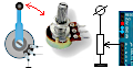
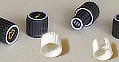
Hardware implementation
Most of input controls and output displays for radio equipment in the HCSCI are custom HCSCI functions, that are unified for all instrument groups, but provide specific functionality for different device types.
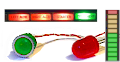
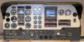
1. You can use the full HCSCI Panel for your plane with any of listed radio devices and control them with mouse (or touch screen )
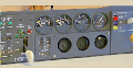
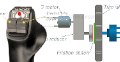
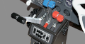
2. You can use the HCSCI Panel for your plane with radio devices displaying on the monitor acreen and control them with real buttons/knobs placed on the cover plate. In this case you can use full visual functionality for every device display.
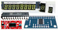
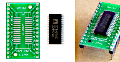
3. You can make fully hardware devices with 7-segment displays or LCDs and control them with real buttons/knobs placed on the cover plate.
In this case, you can display only the main functions with limitations defined by the displays used.
As example, below is the description of all supported functions for KX155A/165A radio.
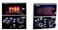
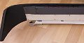
Com/Nav Radio SVC-165A
This Com/Nav device is developed for our HCSCI Panel and have all on-screen controls working. But also you can use real buttons and encoders with HCSCI Panel or replicate the full KX165A unit in real module using 7-segment/LCD displays and HCSCI parameters from the configurator list or image-map.
This custom HCSCI functions (added in v0.9.47) provides fully functional Com/Nav device. You don't need to have a plane model that supports this type of radio panel, all it's functions will be working independetly of the plane model.
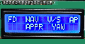
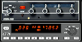
HCSCI 165A Comm Radio Controls and functions
HCSCI 165A Comm Radio modes:
Normal Mode: Left/Right display show current Active and Standby Comm frequencies.
Click the Xfer [<->] button to flip Active and Standby displays.
Direct Active Entry mode:
Press and hold the Xfer [<->] button more than 2 seconds.
The Standby display is blank
Use the frequency change encoders to set the active frequency directly.
Exit to normal mode - Press the Xfer [<->] button momentary.
Write pre-selected frequencies to the memory ( up to 32 channels):
Press and hold the [CHAN] button for more than 2 seconds.
The PG annunciator appers with channel number flashing, that means you can select needed channel with inner rotary knob (khz knob).
In the "Standby" display you will see either 3 dashes (---) if selected channel has no saved frequency or the frequency saved before in this channel.
When needed channel number is selected click the Xfer [<->] button.
The channel number display stops flashing and the Standby display start flashing, that means you can adjust the channel frequency now with frequency change rotary knobs.
When you have set needed frequency, you can continue for other channels:
click the Xfer [<->] button and then select next channel, click the Xfer [<->] button again and set needed frequency and so on...
To exit from this mode click the [CHAN] button. All entered channel data will be saved in memory.
Read frequency from the memory to Standby diplay:
Press the [CHAN] button momentary.
The [CH] annunciator appears
The snadby display shows the frequency from the currently selected channel or [---] if this channel has no saved data.
Use the inner knoab to select channel number and use it asfor current "Standby" frequency.
After 5 seconds of inactivity the device will return to normal mode with new frequency displayed in the standby window.
If an empty channel [---] was selected before this, the old standby frequency will return back to display.
The "R" annunciator is active when the message is receiveng from ATC and "T" is lit during the transmit mode of operation.
HCSCI 165A NAV Radio modes:
Normal Mode: Left/Right display show current Active and Standby NAV frequencies.
Click the Xfer [<->] button to flip Active and Standby displays.
Direct Active Entry mode:
Press and hold the Xfer [<->] button more than 2 seconds.
The Standby display is blank
Use the frequency change knobs to set the active Nav frequency directly.
Exit to normal mode - Press the Xfer [<->] button momentary.
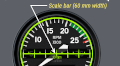
CDI (Course Deviation Indicator) VOR/LOC Mode:
Note: this indicator is independent of any OBS course selected on an external CDI (VOR/HSI).
Press the [MODE] button momentary when device is in "normal" mode.
The CDI horizontal scale will be displayed below the frequency window.
You can use the Nav tune knobs to set the Active Nav frequency directly and Xfer [<->] button to flip the "blind" standby and active frquencies.
When the active frequency is tuned to a VOR, the center of the CDI scale displays the “TO” or “FROM” indicator and "standby"
window displays the OBS course.
To select desired OBS course, pull out the inner NAV frequency knob and rotate it.
An [OBS] in the middle of the NAV display is flashing when the inner NAV frequency knob is pulled out.
If the active frequency is tuned to a localizer frequency (LOC, ILS), the standby window displays "LOC" message
and the LOC marks (> <) in the center of the deviation scale.
When the horizontal signal is not receiving or too wheak, the "FLAG ---" message will be displayed instead of deviation scale.
BEARING display mode:
Press the [MODE] button momentary to switch to the "Bearing" mode (the next after the "CDI" mode)..
The "stanby" display shows the current Bearing cource TO the station (or "---" flag if the signal is too weak).
You can use the Nav tune knobs to set the Active Nav frequency directly and Xfer [<->] button to flip the "blind" standby and active frequencies.
RADIAL display mode:
Press the [MODE] button momentary to switch to the "Radial" mode (the next after the "Bearing" mode)..
The "stanby" display shows the current Radial cource FROM the station (or "---" flag if no signal)..
You can use the Nav tune knobs to set the Active Nav frequency directly and Xfer [<->] button to flip the "blind" standby and active frequencies.
TIMER display mode:
Note: when the unit power is turned ON, the elapsed timer begins counting from zero.
Press the [MODE] button momentary to switch to the timer mode (the next after the "Radial" mode).
STOP and RESET the timer: Press and hold the Xfer [<->] button for more than 2 seconds.
The "ET" annunciator start to flash.
START timer - Press the Xfer [<->] button momentary.
You can set the "Countdown" timer after reset: when the "ET" is flashing you can use the NAV tune knoabs to set the desired countdown time (in minutes:seconds).
The outer knob sets minutes, the inner knob sets tens of seconds or ones seconds (when knob is pulled out).
 System description, plugin/firmware download